A flow meter is an instrument used to measure the flow rate of fluids, including water, chemicals, air, or gas, within a pipeline system. When a flow meter shows abnormal or inconsistent readings, the issue is not always due to equipment malfunction; often, it results from improper installation.
It’s essential to understand that there are various types of flow meters, each with slightly different installation requirements depending on their measurement principle. This article outlines general best practices for installing flow meters and provides specific recommendations for the common types.
The simplest way to install a flow meter correctly is to follow the manufacturer’s installation manual. In addition to the device-specific instructions, many types of flow meters benefit from adhering to general best practices that help minimize measurement errors caused by poor installation.
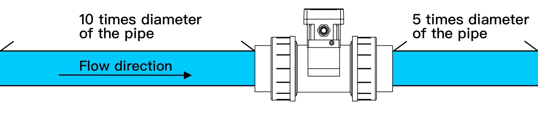
1 ) At least 10D in the front and 5D behind
To ensure stable and accurate readings, it’s recommended to provide sufficient lengths of straight pipe before and after the flow meter. As a general rule, the upstream section should have at least 10 times the pipe diameter (10D) of straight, unobstructed pipe, and the downstream section should have at least 5 times the pipe diameter (5D).
Why is this important?
Studies show that installing a flow meter immediately downstream of a pipe elbow (or other disturbances) often leads to greater measurement deviations. This is because upstream bends or fittings disrupt the flow profile, causing turbulence and swirl that affect measurement accuracy. By reserving adequate straight pipe runs, you allow the flow to stabilize, which helps reduce turbulent effects and ensures more reliable readings.
[1]
Assuming the pipe's inner diameter (ID) is 4 cm, let's apply the "At least 10D in the front and 5D behind" rule to determine the required lengths of the straight pipe segments:
• Upstream (Flow-in) Straight Pipe Segment Length:
10 × ID = 10 × 4 cm = 40 cm
• Downstream (Flow-out) Straight Pipe Segment Length:
5 × ID = 5 × 4 cm = 20 cm
For a pipe with an inner diameter of 4 cm, the ideal installation position for the flowmeter would require an upstream straight pipe segment of 40 cm and a downstream straight pipe segment of 20 cm.
If the inner diameter (ID) is unknown, the outer diameter (OD) can be used along with the wall thickness to calculate the ID:
Formula: ID = OD − 2 × Wall Thickness
[2]
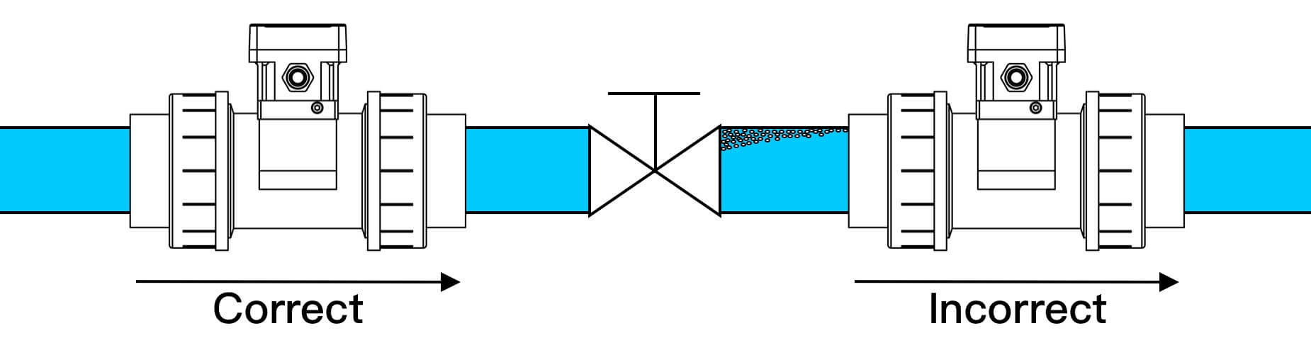
2 ) Avoid Installing Downstream of Valves or Pumps
Disturbing elements in a pipeline system include pumps, control valves, reducers, expanders, and other fittings that disrupt the flow profile. To ensure measurement accuracy, it’s strongly recommended to install the flow meter upstream of control valves and at a sufficient distance from pump outlets.
Based on industry experience, placing a flow meter before a valve is preferable because valves can create downstream flow disturbances, including turbulence, cavitation, or pressure fluctuations, which can compromise measurement accuracy.
If site conditions make it unavoidable to install the flow meter downstream of a pump or valve, it’s advised to substantially increase the upstream straight pipe length, often to at least 30 pipe diameters (30D) or more, to allow the flow profile to recover before entering the meter.
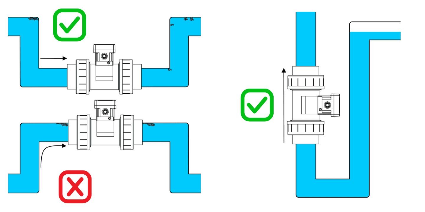
3 ) Install on Upward Flowing or Low-Point Full Pipe Sections
The flow meter should be installed at a location where the pipe remains completely full of liquid during operation. Avoid placing the meter at the highest point of the piping system, where air pockets are likely to accumulate near the sensor and cause inaccurate readings.
The ideal installation locations are at the low point of a U-shaped pipe section or on vertical pipe segments with upward flow direction. These positions help ensure the pipe remains fully filled with liquid, preventing empty pipe conditions and avoiding measurement errors.
4 ) Avoid Vibration-Prone Areas; Use Protective Covers for Outdoor Installations
Unless you are using a flow meter specifically designed for high-vibration or extreme environmental conditions, it’s best to avoid installing flow meters in locations with excessive mechanical vibrations. For electromagnetic flow meters, it’s also important to keep them away from equipment that generates strong magnetic fields, as electromagnetic interference can affect zero stability and measurement accuracy.
When installing flow meters outdoors, it is recommended to install them under protective covers or shelters. This helps shield the equipment from direct sunlight, extreme temperatures, heavy rainfall, or snow, all of which can impact measurement performance and potentially shorten the lifespan of the device.
Ultrasonic Flow Meters
Ultrasonic flow meters can be categorized by measurement principle into transit-time type and Doppler type.
• Transit-time ultrasonic flow meters calculate flow by measuring the time difference of ultrasonic waves traveling upstream and downstream. These meters require clean liquids free of bubbles or solid particles, as such disturbances can interfere with the ultrasonic signal.
• Doppler ultrasonic flow meters, on the other hand, are designed for fluids that contain bubbles or suspended solids, using frequency shifts from particles or gas to estimate flow.
➜Learn more:
Understanding Z, V, N, and W installation modes
For integrated clamp-on ultrasonic flow meters (all-in-one design), the need for coupling gel is eliminated, simplifying the installation process. For example, LORRIC’s FU-ES clamp-on ultrasonic flow meter is designed as a convenient solution to help field personnel achieve easy and efficient installation.
➜ Learn more about the
FU-ES Clamp-On Ultrasonic Flow Meter.
Paddle Wheel Flow Meters
Paddle wheel flow meters measure flow by detecting the rotation of a small impeller or paddle that is driven by the moving fluid. These meters are sensitive to particulate matter or debris in the medium, so it is recommended to install a strainer or filter upstream to prevent solid particles from jamming the paddle wheel, which can lead to measurement errors, system blockage, or even damage.
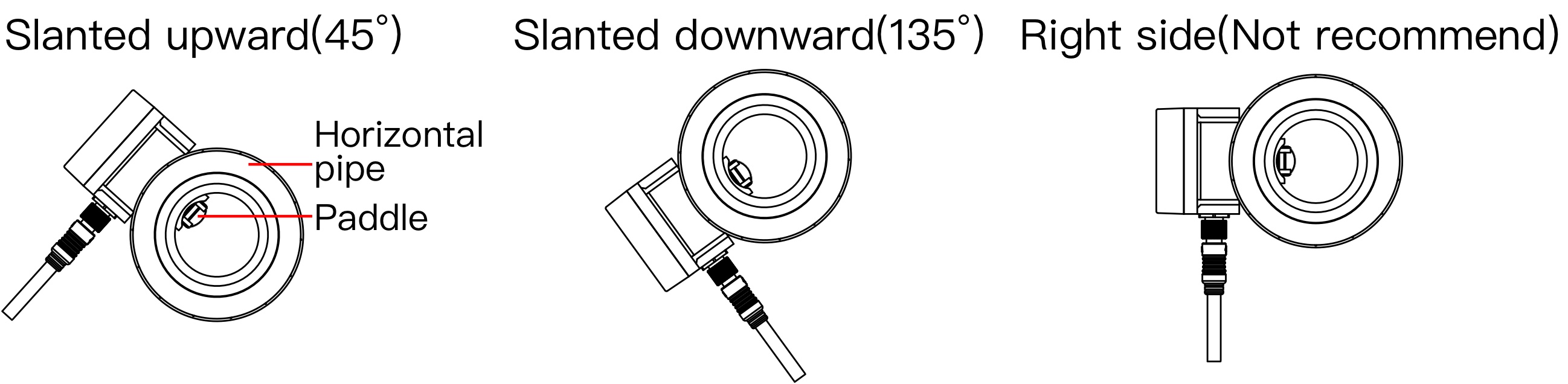
The installation angle of a paddle wheel flow meter is also critical. The best practice is to install the meter on a horizontal pipe section at a 45° or 135° angle, rather than at the very top (12 o’clock), bottom (6 o’clock), or exact side (3 or 9 o’clock) of the pipe.
•Top-mounted positions may trap air bubbles, which can get caught in the paddle and disrupt readings.
•Bottom-mounted positions can expose the paddle to sediment buildup, causing blockage or wear.
•Side-mounted positions can lead to uneven wear, especially on ceramic components, due to asymmetric flow forces.
Electromagnetic Flow Meters
Electromagnetic (magnetic) flow meters are designed to measure the flow of electrically conductive liquids. When installing a magnetic flow meter, it’s crucial to ensure that the pipe remains completely full of liquid at all times and is free of air bubbles, as empty pipe conditions or entrained air can cause significant measurement errors.
The electrodes of the meter should be installed horizontally (aligned at the 3 and 9 o’clock positions) to avoid exposure to air pockets at the top of the pipe or sediment buildup at the bottom, both of which can interfere with accurate signal detection.
Additionally, proper grounding is essential for electromagnetic flow meters to prevent electrical noise from affecting the sensor signals. Installers should avoid placing the meter near strong electromagnetic interference sources, such as large electric motors or variable frequency drives (VFDs), which can cause zero-point drift or unstable readings.
[8]