Overview
- Understanding the principles behind various flow meters is crucial for fluid monitoring. This article introduces the working principles of a variety of flow meters, including ultrasonic, variable area, Coriolis, paddle wheel, positive displacement, vortex, turbine, differential pressure, laminar flow, electromagnetic, and thermal mass flow meters. These meters utilize different physical phenomena and technologies, suitable for a wide range of fluid measurement applications.
Flow meters are widely used and versatile instruments in fluid processing systems, from agricultural chemical production to water treatment facilities. They monitor operational efficiency and provide data to detect potential pipeline issues. This article focuses on understanding the working principles of different flow meters. For information on their pros, cons, and selection tips, refer to "
Flowmeter Selection Guide - The Pros and Cons of 11 Types of Flowmeters"
Ultrasonic Flow Meters
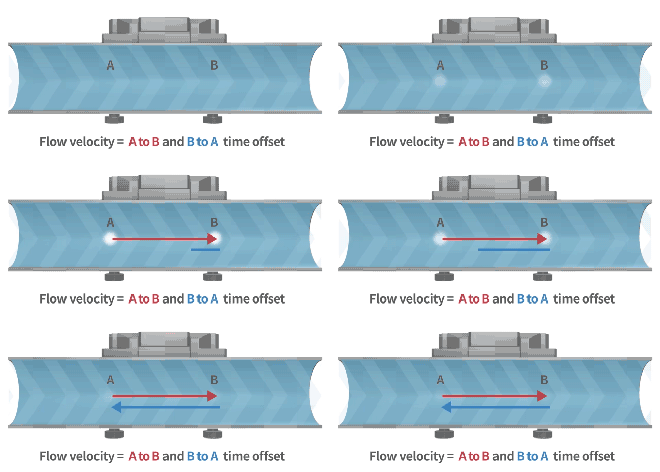
An ultrasonic flow meter calculates flow rate using the transit-time method. Ultrasonic waves travel faster and with reduced transit time in the direction of flow, while in the opposite direction, they travel slower, increasing the transit time. By measuring this time difference, the flow velocity of the fluid is determined (as illustrated in the diagram).
Some ultrasonic flow meters utilize the Doppler method, based on the Doppler effect. When ultrasonic waves encounter particles or bubbles moving within the fluid, the reflected frequency shifts. By measuring this frequency shift, the flow velocity can be calculated.
▪ Learn more:
LORRIC Taiwan-Made Patented Ultrasonic Flow Meter with One-Click Activation.
Variable Area Flow Meters (Rotameters)
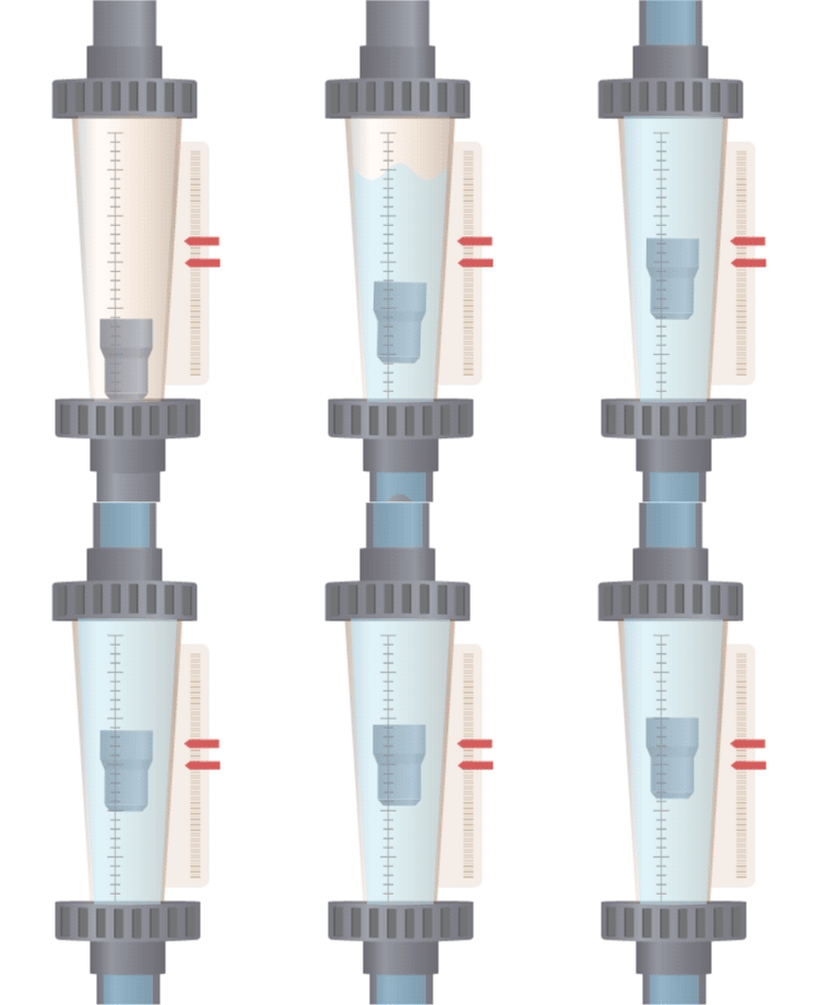
A float is suspended in a tapered tube (wider at the top, narrower at the bottom). When fluid flows through the tube, it creates a pressure difference, generating an upward force that balances with the weight of the float in a stable equilibrium region. As the flow rate increases, a larger cross-sectional area is needed to support the float at equilibrium, which means the float will rise to a higher position with increased flow. Therefore, a variable area flow meter (rotameter) measures flow rate by observing the change in cross-sectional area at which the float stabilizes.
▪ Learn more: LORRIC Taiwan-Made Patented Pointer Rotameter Flow Meter
[2]
Coriolis Flow Meters
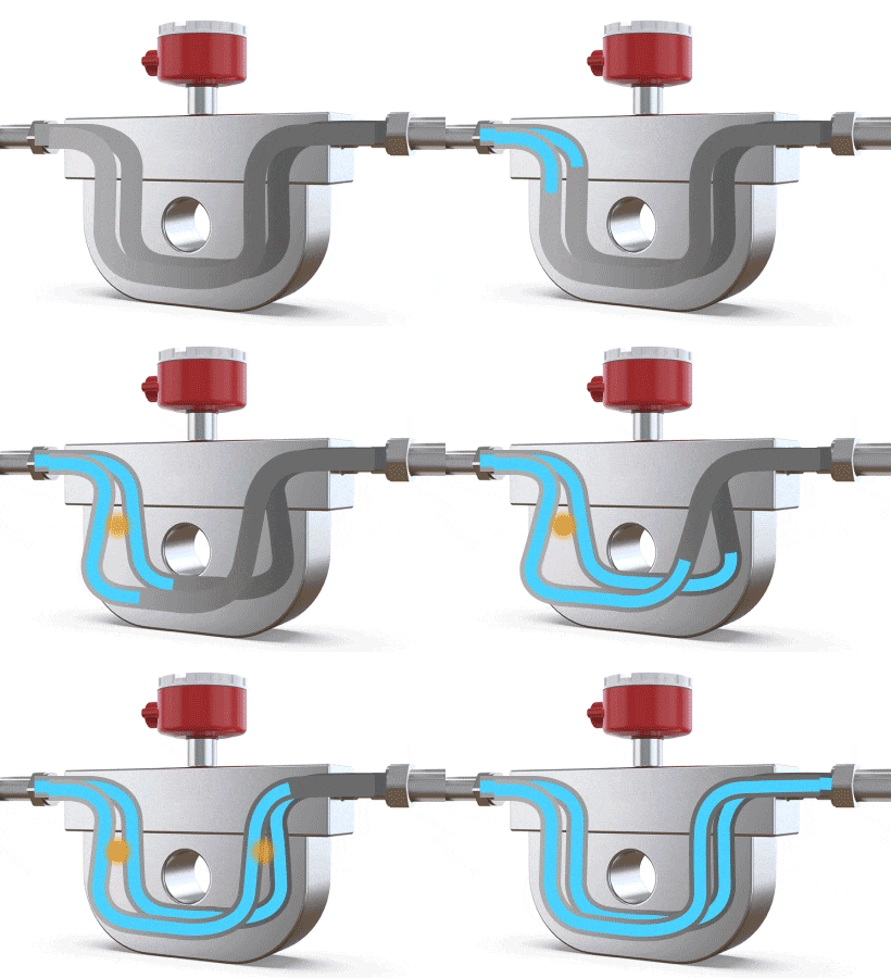
A Coriolis flow meter measures mass flow rate by leveraging the physical phenomenon of Coriolis force (where a particle moving in a straight line within a rotating system, and not parallel to the rotation, experiences a deviation in its trajectory due to the system's inertia). When fluid flows through a U-shaped tube, the Coriolis force causes the tube to twist slightly and vibrate. The difference in flow direction between the inlet and outlet leads to a twisting of the U-shaped tube. Sensors placed near the inlet and outlet detect and calculate these vibrations. By analyzing the amplitude and frequency of the vibrations, the mass flow rate and fluid density can be determined, making it a flow meter specifically for mass flow measurement.
▪ LORRIC offers a wide variety of flow meters,
feel free to leave us a message for consultation!
Paddle Wheel Flow Meters
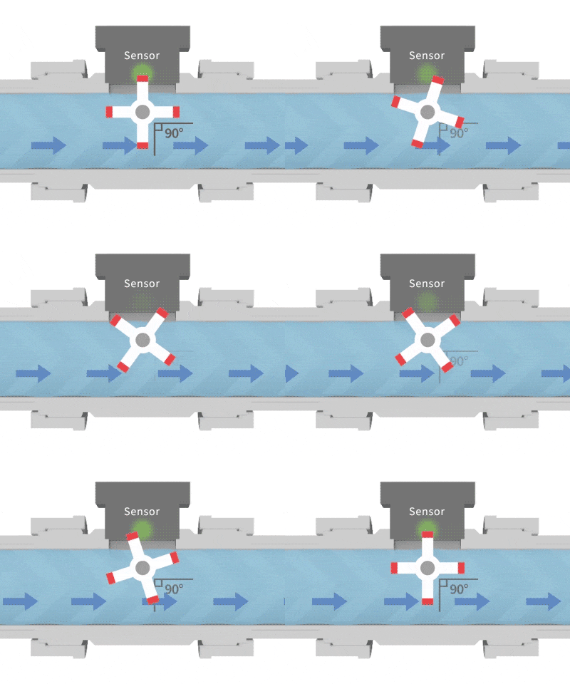
Similar to the structure of a waterwheel, fluid passing through causes it to rotate. Magnetic metal components embedded in the blades generate pulsed signals, which are detected by a sensor. By counting these pulses, the flow velocity can be converted into flow rate. The calculation method for a paddle wheel flow meter: Flow per pulse × Number of pulses ÷ Time = Instantaneous flow rate.
▪ Learn more: LORRIC Taiwan-Made 30x Output Patented Paddle Wheel Flow Meter
[4]
Positive Displacement Flow Meters
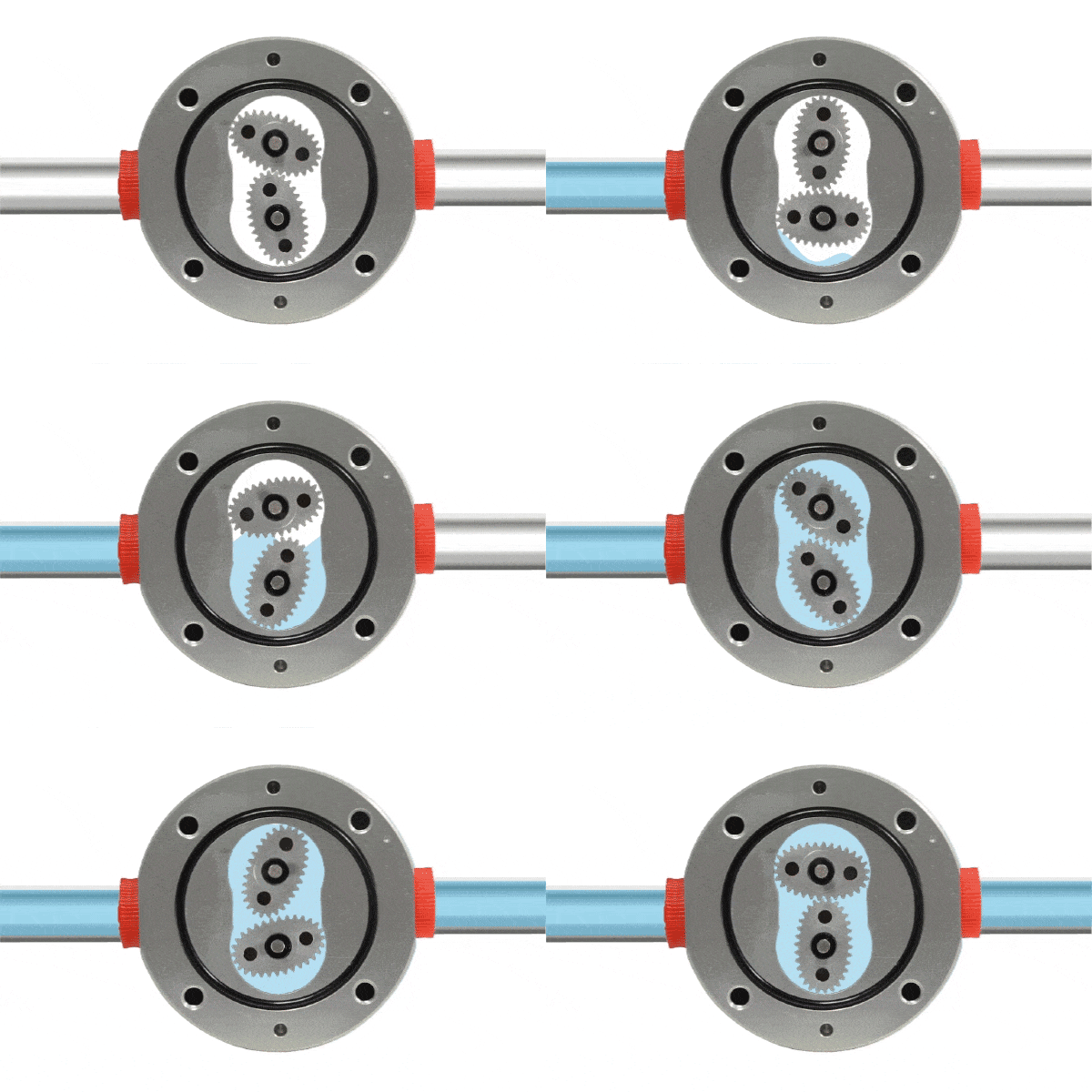
A positive displacement flow meter features a fixed small volume chamber (commonly referred to as a metering chamber) that measures flow by repeatedly calculating the volume of fluid passing through this chamber. Within the metering chamber, gears (rotating components) are installed. As fluid passes through the flow meter, a pressure differential is created at the inlet and outlet, driving the rotation of the gears and pushing the fluid continuously toward the outlet.
Since the chamber volume is fixed, measuring the number of gear rotations allows for precise determination of the fluid volume passing through the flow meter. Generally, the gears are designed to be highly chemically resistant. Positive displacement flow meters are characterized by their high-pressure differential capability, suitability for highly viscous liquids, and high accuracy.
▪ LORRIC offers a wide variety of flow meters,
feel free to leave us a message for consultation!
Vortex Flow Meters
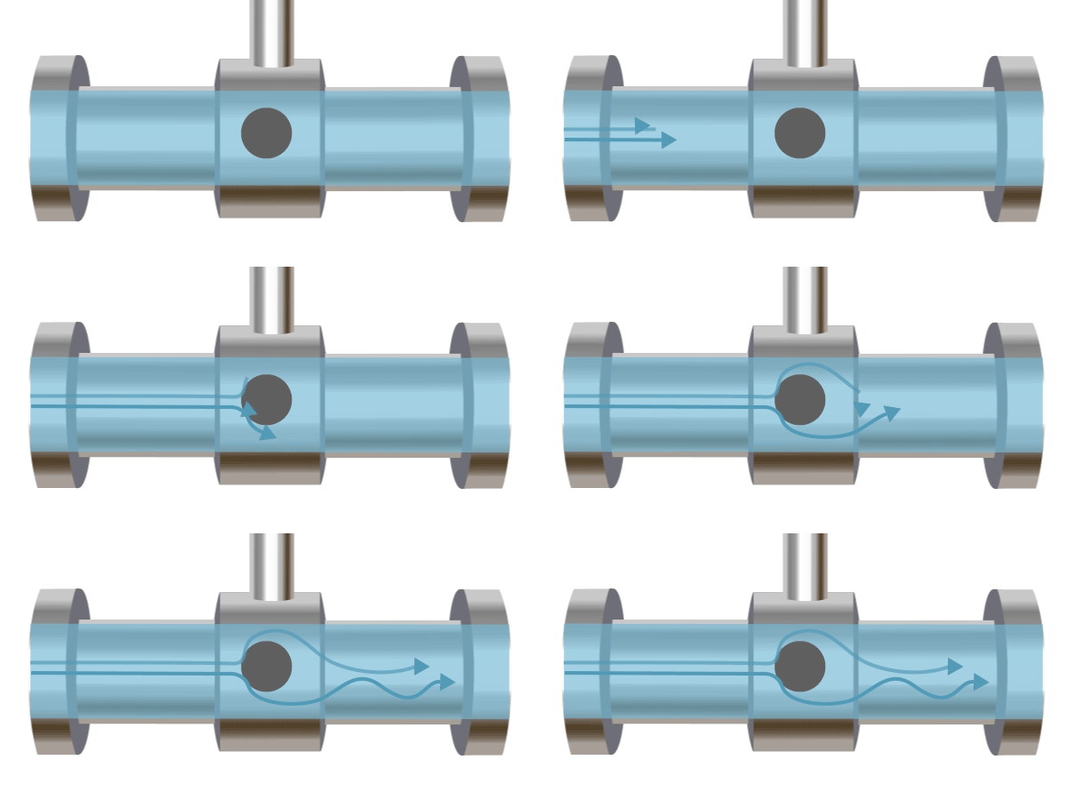
A vortex flow meter operates based on the Kármán vortex street principle, named after Hungarian-American engineer and physicist Theodore von Kármán, who first theoretically described it in 1912. An obstruction is placed in the pipe, and as fluid flows past this obstacle, vortices are formed downstream. The frequency of vortex formation is proportional to the flow velocity. Typically, ultrasonic methods are used to measure the vortex frequency, which is then used to calculate the flow rate.
▪ LORRIC offers a wide variety of flow meters,
feel free to leave us a message for consultation!
Turbine Flow Meters
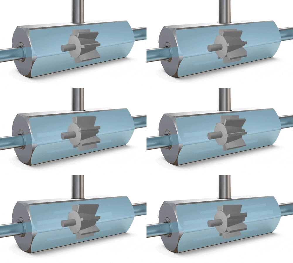
A turbine is positioned at the center of the flow meter’s pipe. As fluid flows through, it exerts force on the turbine blades, causing them to rotate. Once a stable rotational speed is reached, it becomes directly proportional to the flow velocity. Magnetic detection produces pulse signals, which are converted by sensors to calculate the flow rate. The RPM (revolutions per minute) is directly proportional to the flow rate, and the number of revolutions is proportional to the total volume passed through.
▪ LORRIC offers a wide variety of flow meters,
feel free to leave us a message for consultation!
Differential Pressure Flow Meters
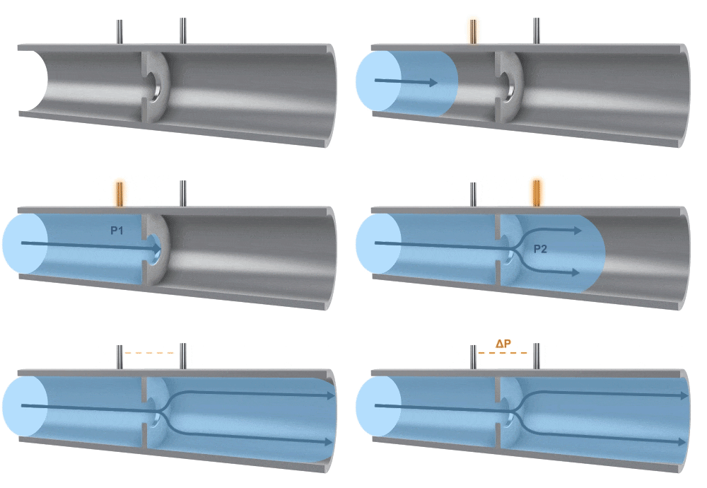
A differential pressure (also known as throttling) flow meter measures flow by utilizing the pressure difference created when fluid passes through a throttling device. By using a precisely machined orifice, the pressure is measured at both the inlet and the outlet. The differential pressure between the inlet and outlet across the orifice is used to determine the flow rate. The flow velocity is also related to the size of the orifice.
▪ LORRIC offers a wide variety of flow meters,
feel free to leave us a message for consultation!
Laminar Flow Meters
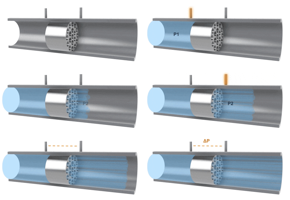
A differential pressure flowmeter, composed of sensors and a differential pressure gauge, measures flow by detecting the pressure difference at both ends of the sensor. The principle is that, due to the influence of adhesive forces, fluid flow causes energy losses in pressure. During a stable flow process, there is a fixed relationship between pressure loss, fluid viscosity, and flow rate. The differential pressure (△P) has a linear relationship with volumetric flow rate (Qv). This type of flowmeter is mainly used for measuring small flows, but when applied to high-viscosity fluids, it is important to maintain a stable laminar flow state.
▪ LORRIC offers a variety of flowmeters,
feel free to leave a message for consultation!
Electromagnetic Flow Meters
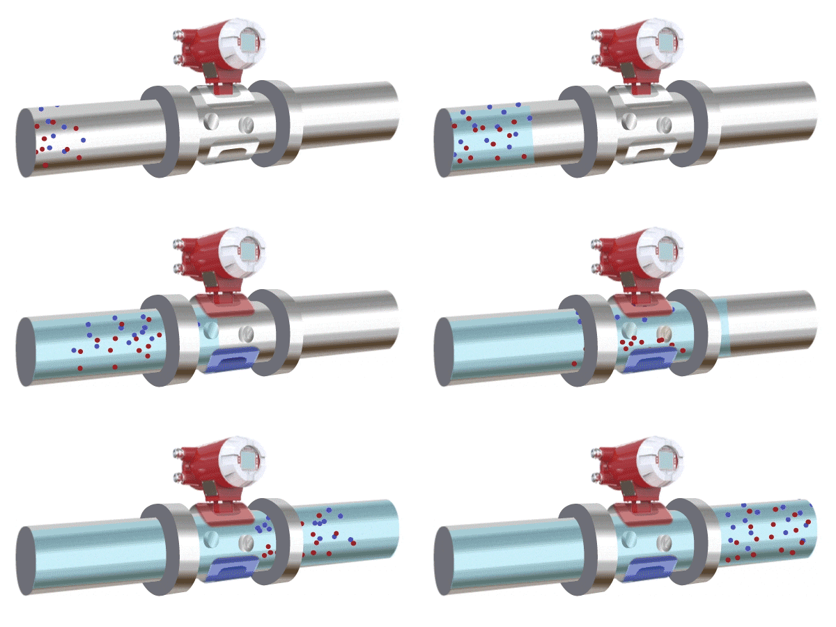
An electromagnetic flow meter operates based on the principle of electromagnetic induction. It measures the flow of a conductive fluid by detecting the electromotive force generated as the fluid passes through an applied magnetic field. A coil installed on top of the pipeline generates a magnetic field, and the fluid must contain charged ions. As the fluid passes through the magnetic field, it induces a voltage across the two sides of the pipe. This electromotive force is proportional to the average flow velocity and is used to calculate the flow rate.
▪ LORRIC offers a wide variety of flow meters,
feel free to leave us a message for consultation!
Thermal Mass Flow Meters
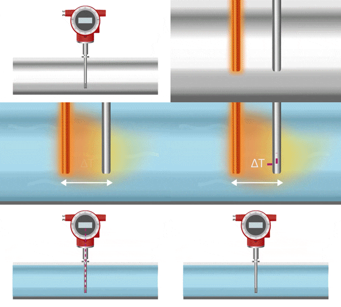
A thermal mass flow meter consists of two tubes (or other heatable objects) placed within the fluid. One of these tubes is heated, and as the fluid comes into contact with the heated tube, it carries away heat, which in turn increases the temperature of the fluid. By measuring the temperature changes across the two tubes, the flow rate can be determined. This principle generally requires a longer time to reach a stable state.
▪ LORRIC offers a wide variety of flow meters,
feel free to leave us a message for consultation!